Mini Composite PC Controller Design Based on ESP8266
Motivation
After finally taking a vacation, I decided to set up an E3 platform for fun. I wanted to turn it into a server while saving power during idle times. I found an ESP8266 (WeMos D1 R1) that had been collecting dust in my dev board collection, so I used it.
Requirements
- Control PC power: long press power button, short press reset button, and read power status
- Receive and log syslog data from COM port
- Provide serial console functionality
Read hard disk LED and buzzer
Requirement 1 is straightforward. Based on Intel's front panel IO design documentation and practical testing, buttons are 3.3V pull-up inputs, while the power LED is a push-pull 5V output. The COM port should technically be RS232 level, but my motherboard (Z270-Dragon) doesn't expose it; instead, it uses a COM_Debug port which happens to be TTL level. Serial console is easiest—the board's CH340 chip directly connects to USB for ttyUSB.
As for requirement 4, I originally planned to implement it, but the hard disk LED is a push-pull PWM 5V output, and the buzzer is a mystery—possibly open-drain. The ESP8266 only has about 5 usable IO pins (despite having many more physical pins, many have special startup requirements). Adding support would require scraping the board and adding voltage divider circuits. Moreover, the hard disk LED isn't essential (who looks at it normally?), and if the buzzer sounds, it indicates a low-level hardware issue that can't be fixed remotely anyway.
Hardware Design and Wiring
First, regarding power supply: all our IO is inside the chassis, so we can directly use 5VSB; of course, where to find 5VSB on the motherboard depends on the specific model. If worst comes to worst, we can route a wire from the ATX connector! We must also disconnect the USB power, otherwise shorting 5V and 5VSB would be problematic.
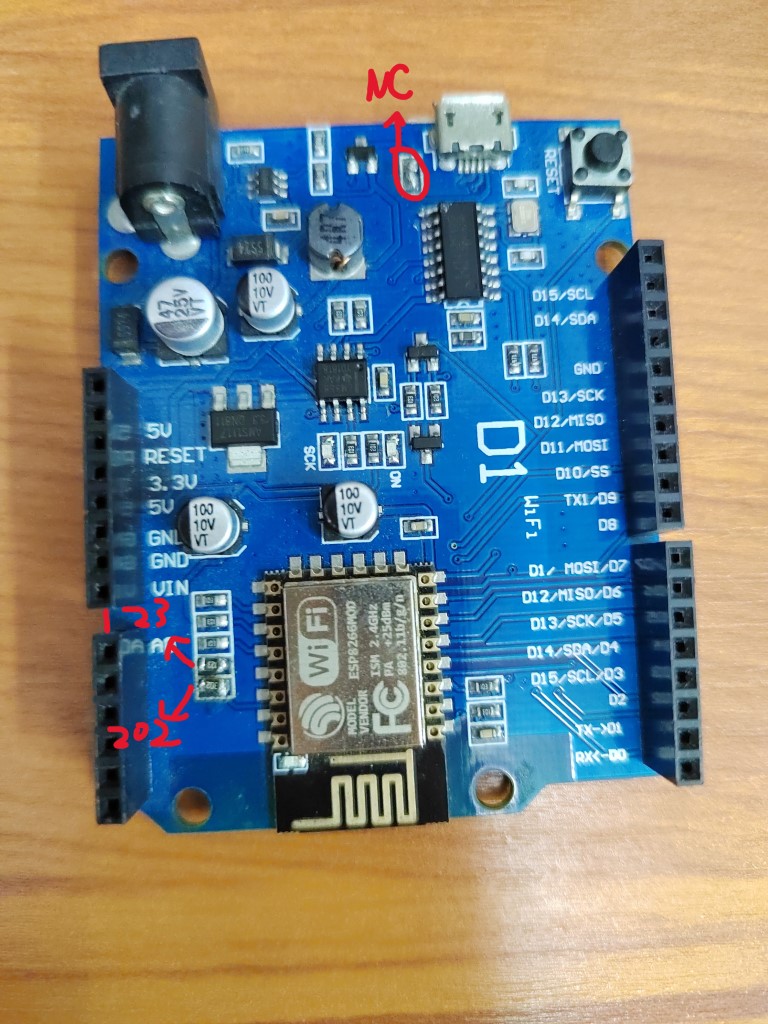
Next is the voltage level issue for the power LED. It's a 5V push-pull output, so we need voltage division. On this board, the A0 interface has a voltage divider circuit. The ESP8266 receives only 1V. The original design used 104 and 224 resistors to divide 3.3V to 1V. We simply changed it to use 202 and 123 resistors to divide 5V.
Modification shown below:
Next, we can allocate the IO pins:
| ESP8266 | Function |
|---|---|
| D0 D1 (3 1) | Serial Console |
| TX1 (2) | Debug Logger |
| SCK (14) | To PWR_BTN |
| MISO (12) | To RST_BTN |
| A0 (17) | From PWR_LED |
| MOSI SS (13 15) | To COM_Debug |
Also, some ASUS motherboards define COM_Debug like this:
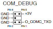
After testing, my motherboard happened to match this definition :smile
Warning
Standard COM ports on motherboards typically follow the RS232 specification, which means their voltage levels are incompatible with TTL levels. In that case, you'll need a level conversion chip.
Software Design
Interface and Commands
Port 23 is assigned for serial forwarding, and port 22 for the console.
Power control commands use # as prefix and $ as suffix, with the middle character being: R - short reset, P - long press power button, S - short press power button.
Then there's L to list all log files, and codes greater than 0x80 for reading logs by index.
D to enable/disable COM real-time output, M to get current status, V to get version info.
Serial Forwarding
Based on the WiFiToSerial example project, with minor modifications and wrapped in a class.
Since ESP8266 has only one usable receive serial port, we use the swap function to switch pins. When the serial console port connects, we cut off logging and map to USB serial; otherwise, we map to COM.
Logging
Based on LittleFS for chunked log files. The 3MB storage is divided into 64K chunks with over 90 files max, providing some limitation for single-character command reading. Due to LittleFS's power-loss safety design, we must periodically sync to ensure writes are visible. We also handle file size checking and deletion of old files at the same time.
WiFi Management and Configuration
Using the WiFiManager library for automatic WiFi connection and providing a Config Portal on failure. We also register a disconnect event handler to restart the ESP8266.
Afterword
During installation, I discovered that after the system boots, a longer power button press is needed to force shutdown. Also, the signal inside the all-metal chassis was too poor, requiring repositioning, such as near the front panel seams...
Source code available at repository.